

حل جميع مشاكل السيرفر Fix PowerEdge RAID Controller Errors
Issue 1: Troubleshooting a Hard Drive
If your system has a RAID controller and your hard drives are configured in a RAID array, perform the following steps:
- Restart the system and press <F10> during system startup to run the Lifecycle Controller, and then run the Hardware Configuration Wizard to check the RAID configuration.
- Ensure that the hard drive(s) have been configured correctly for the RAID array.
- Take the hard drive offline and reseat the drive.
- Exit the configuration utility and allow the system to boot to the operating system.
- Ensure that the required device drivers for your controller card are installed and are configured correctly.
- See the Operating System documentation for more information.
- Restart the system and enter the System Setup.
- Verify that the controller is enabled and the drives are displayed in the System Setup.
Issue 2: Rebuilding a Failed Physical Disk
Issue:
Rebuilding a physical disk after one of them is in a failed state.
Corrective Action:
If you have configured hot spares, the PERC card automatically tries to use one of them to rebuild a physical disk that is in a failed state. Manual rebuild is necessary if no hot spares with enough capacity to rebuild the failed physical disks are available. You must insert a physical disk with enough storage in the subsystem before rebuilding the physical disk.
NOTE: You can use the CONTROLLER BIOS Configuration Utility (<Ctrl> <R>) or Dell OpenManage storage management application to perform a manual rebuild of an individual physical disk.
Issue 3: Smart Errors
SMART monitors the internal performance of all motors, heads, and physical disk electronics and detects predictable physical disk failures.
NOTE: For information about where to find reports of SMART errors that could indicate hardware failure, see the Dell OpenManage storage management documentation at support.dell.com/manuals.
Issue 1: Error Detected On A Physical Disk In A Redundant Virtual Disk
Issue: A SMART error is detected on a physical disk in a redundant virtual disk.
Corrective Action:
- Back up your data.
- Force the physical disk offline.
NOTE: If a hot spare is present, the rebuild starts with the hot spare after the disk is forced offline.- Replace the disk with a new physical disk of equal or higher capacity.
- Perform the Replace Member operation.
NOTE: The Replace Member operation allows you to copy data from a source physical disk of a virtual disk to a target physical disk that is not a part of the virtual disk. For more information about the Replace Member feature, see the topic Using Replace Member and Revertible Hot Spares.
Issue 2: Smart Error Detected On A Physical Disk In A Non-Redundant Virtual Disk
Issue: A SMART error is detected on a physical disk in a redundant virtual disk.
Corrective Action:
- Back up your data.
- Use Replace Member or set up a global hot spare to replace the disk automatically. NOTE: For more information about the Replace Member feature, see the topic Using Replace Member And Revertible Hot Spares.
- Replace the affected physical disk with a new physical disk of equal or higher capacity.
- Restore from the backup.
Issue 4: Foreign Configuration
When a foreign configuration is present, you can select Foreign Configuration View to display the configuration. The screen shows the foreign configuration as it would be if you import it. You can preview the foreign configuration before you decide whether to import it or clear it.
In some cases, a foreign configuration cannot be imported. If a physical disk in a virtual disk is rebuilding, the physical disk's state is set to Rebuild. No virtual disk target ID displays for virtual disks that cannot be imported.
The section Importing or Clearing Foreign Configurations Using the Foreign Configuration View Screen contains the procedures you can use to manage the foreign configurations.
NOTE: The CONTROLLER BIOS Configuration Utility (<Ctrl> <R>) reports error codes for failed imports of foreign configurations.
Foreign Configuration Found Error Message
Foreign configuration(s) found on adapter. Press any key to continue, or ’C’ to load the configuration utility or ’F’ to import foreign configuration(s) and continue.Probable Cause:
When a controller firmware detects a physical disk with existing foreign metadata, it flags the physical disk as foreign and generates an alert indicating that a foreign disk was detected.
Corrective Action:
Press <F> at this prompt to import the configuration (if all member disks of the virtual disk are present) without loading the CONTROLLER BIOS Configuration Utility (<Ctrl> <R>). Or press <C> to enter the CONTROLLER BIOS Configuration Utility (<Ctrl> <R>) and either import or clear the foreign configuration.
Foreign Configuration Not Found In <Ctrl> <R> Error Message
The foreign configuration message is present during POST but no foreign configurations are present in the foreign view page in <Ctrl> <R>. All virtual disks are in an optimal state.Corrective Action:
Ensure all your PDs are present and all VDs are in optimal state. Clear the foreign configuration using <Ctrl> <R> or Dell OpenManage Server Administrator Storage Management.
CAUTION: The physical disk goes to Ready state when you clear the foreign configuration.
If you insert a physical disk that was previously a member of a virtual disk in the system, and that disk’s previous location has been taken by a replacement disk through a rebuild, you must manually remove the foreign configuration flag of the newly inserted disk.
Issue 5: Battery Learn Cycle / Battery or Memory Errors
Battery Transparent Learn Cycle
NOTE: Batteries are only supported on PERC H710, H710P, and H810 cards.
A Transparent Learn Cycle (TLC) is a periodic operation that calculates the charge that is remaining in the battery to ensure there is sufficient energy. The operation runs automatically, and causes no impact to system or controller performance.
The controller automatically performs the TLC on the battery to calibrate and gauge its charge capacity once every 90 days. The operation can be performed manually, if required.
NOTE: Virtual disks stay in Write Back mode, if enabled, during transparent learn cycle. When the TLC completes, the controller sets the next TLC to +90 days.
Memory or Battery Problem Error Message
Memory/Battery problems were detected. The adapter has recovered, but cached data was lost. Press any key to continue.Probable Cause:
The message occurs under the following conditions:
- The adapter detects data in the controller cache that has not yet been written to the disk subsystem.
- The controller detects an Error-Correcting Code (ECC) error while performing its cache checking routine during initialization.
- The controller discards the cache rather than sending it to the disk subsystem because the data integrity cannot be guaranteed.
- The battery may be under charged.
Corrective Action:
Allow the battery to charge fully to resolve this problem.
If the problem persists, contact Dell Technical Support.
Issue 6: Creating Virtual Disk
To watch a 6:23 minute video on creating a virtual disk, refer to the Dell TechCenter YouTube video:
NOTE: Combining SAS and SATA disk drives within a virtual disk is not supported. Also, combining disk drives and SSDs within a virtual disk is not supported.
Perform the following steps to create a virtual disk in the CONTROLLER BIOS:
- During host system bootup, press <Ctrl><R> after the CONTROLLER BIOS screen is displayed.
< > The Virtual Disk Management screen is displayed.
If there is more than one controller, the Main Menu screen is displayed.
Select a controller, and press <Enter>. The Virtual Disk Management screen is displayed for the selected controller.
Use the arrow keys to highlight Controller # or Disk Group #.- Press <F2>. The list of available actions is displayed.
- Select Create New VD and press <Enter>.
The Create New VD screen is displayed.
< > The cursor is on the RAID Levels option.
When adding a virtual disk to a Disk Group, the Add VD in Disk Group screen is displayed.
Skip to step 11 to change the basic settings of the virtual disk.
Press <Enter> to display the possible RAID levels, based on the physical disks available.- Press the down-arrow key to select a RAID level and press <Enter>.
- When creating a spanned virtual disk (RAID 10, 50 or 60), enter the number of physical disks per span in the PD per Span field and press <Enter>.
NOTE: Creating a 22 physical disk RAID 10 VD is possible by selecting RAID 10 and populating the PD per Span field with 22.- Press <Tab> to move the cursor to the list of physical disks.
- Use the arrow key to highlight a physical disk and press the spacebar, <Alt> , or <Enter> to select the disk.
- Select additional disks, if required.
- Press <Tab> to move the cursor to the Basic Settings box.
- Set the virtual disk size in the VD Size field. The virtual disk size is displayed in GB format.
- Press <Tab> to access the VD Name field, and type a virtual disk name.
- Press <Tab> to move the cursor to Advanced Settings.
- Press the spacebar to make the settings active so that you can change them.
< > An X is displayed beside Advanced Settings.
The settings are the stripe element size, read policy, and write policy.
You can also choose Advanced Options such as forcing the cache policy to Write-Back, initializing the virtual disk, and configuring a dedicated hot spare.
The defaults parameters are displayed. You can Accept the defaults or change them.
Back to Top
Issue 7: Virtual Disk Degraded
Virtual Disk Degraded Error Messages and Corrective Actions
Virtual Disks Degraded Error Message
x Virtual Disk(s) Degraded (where x is the number of virtual disks degraded)Probable Cause:
This message is displayed when the CONTROLLER BIOS detects virtual disks in a degraded state.
Corrective Action:
To make the virtual disks optimal, take one the following corrective actions:
- Ensure all disks in the Virtual Disk are present and online.
- Replace any failed disks that may be in the array.
- Correct a hot spare disk, and rebuild the array.
The CONTROLLER BIOS does not take any action.
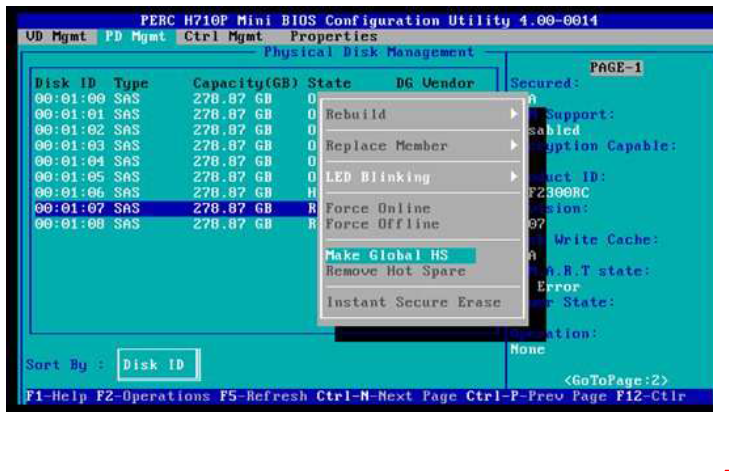
Issue 8: Global Hot Spares
Creating Global Hot Spares
You can use a global hot spare to replace a failed physical disk in any redundant array as long as the capacity of the global hot spare is equal to or larger than the coerced capacity of the failed physical disk.
Perform the following steps to create global hot spares:
Choose the free disk,press F2,and choose Make Global HS
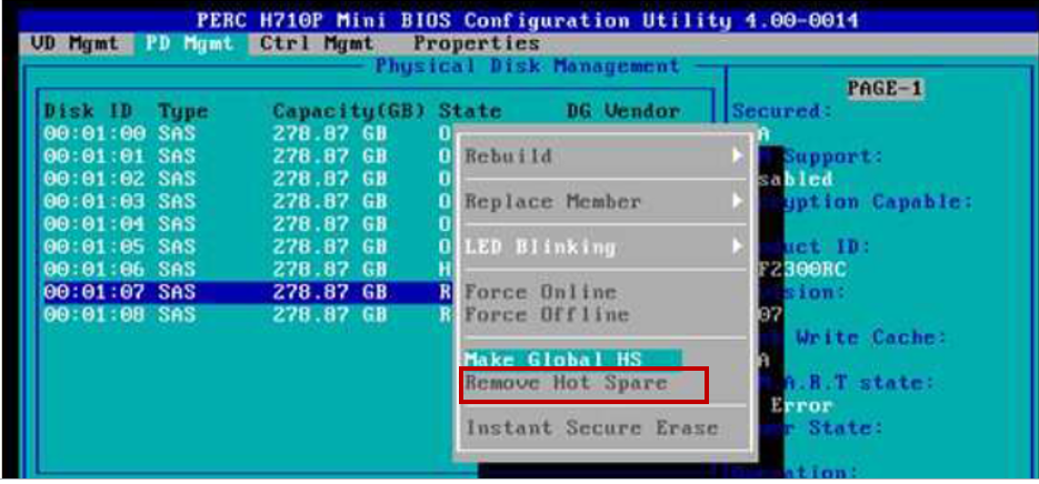
Removing Global or Dedicated Hot Spares
You can remove one global or dedicated hot spare at a time on the PD Mgmt screen. Perform the following steps to remove a global hot spare or dedicated hot spare:
Choose Remove to remove Hot spare
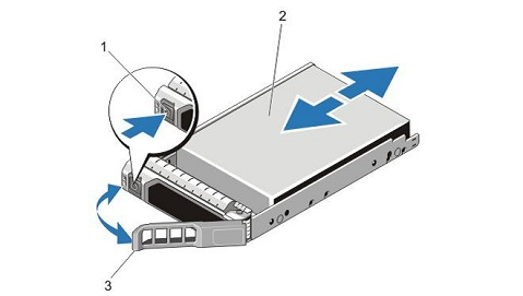
Issue 9: Removal and Installation of Hot Swap Hard Drive
Removing a Hot-Swap Hard Drive
CAUTION: To prevent data loss, ensure that your operating system supports hot-swap drive installation. See the documentation supplied with your operating system.
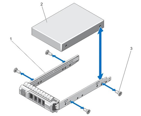
Removing a Hard Drive from a Hard-Drive Carrier
Installing a Hard Drive into a Hard-Drive Carrier
CAUTION: Many repairs may only be done by a certified service technician. You should only perform troubleshooting and simple repairs as authorized in your product documentation, or as directed by the online or telephone service and support team. Damage due to servicing that is not authorized by Dell is not covered by your warranty. Read and follow the safety instructions that came with the product.
Installing a Hot-Swap Hard Drive
CAUTION: Many repairs may only be done by a certified service technician. You should only perform troubleshooting and simple repairs as authorized in your product documentation, or as directed by the online or telephone service and support team. Damage due to servicing that is not authorized by Dell is not covered by your warranty.
Read and follow the safety instructions that came with the product.
CAUTION: Use only hard drives that have been tested and approved for use with the hard-drive backplane.
CAUTION: Combining SAS and SATA hard drives in the same RAID volume is not supported.
CAUTION: When installing a hard drive, ensure that the adjacent drives are fully installed. Inserting a hard-drive carrier and attempting to lock its handle next to a partially installed carrier can damage the partially installed carrier's shield spring and make it unusable.
CAUTION: To prevent data loss, ensure that your operating system supports hot-swap drive installation. See the documentation supplied with your operating system.
CAUTION: When a replacement hot-swappable hard drive is installed and the system is powered on, the hard drive automatically begins to rebuild. Make absolutely sure that the replacement hard drive is blank or contains data that you wish to have over-written. Any data on the replacement hard drive is immediately lost after the hard drive is installed.
Click here to watch an 11 second video on Removing and Installing a Hot Swap Hard Drive in Your R720.
- Ensure all disks in the Virtual Disk are present and online.
- Replace any failed disks that may be in the array.
- Correct a hot spare disk, and rebuild the array.
- Press the down-arrow key to highlight a physical disk to change to a global hot spare.
- Press <F2> to display the menu of available actions.
- Press the down-arrow key to highlight Make Global HS and press <Enter>.
The physical disk is changed to a global hot spare. The status of the physical disk as a global hot spare is displayed under the heading State.
NOTE: To replace a failed physical disk global hot spares must use the same disk technology and must be equal or greater in size.- Select additional physical disks if desired and follow the previous steps to change them to global hot spares.
- Press <Ctrl> <N> to access the PD Mgmt screen.
A list of physical disks is displayed. The status of the each disk is displayed under the heading State.- Press the down-arrow key to highlight a physical disk that is a hot spare.
- Press <F2> to display the menu of available actions.
- Press the down-arrow key to select Remove Hot Spare from the list of actions and press <Enter>.
The physical disk is changed to the Ready state. The status of the physical disk is displayed under the heading State.
NOTE: Try to use physical disks of the same capacity in a specific virtual disk. If you use physical disks with different capacities in a virtual disk, all physical disks in the virtual disk are treated as if they have the capacity of the smallest physical disk.- Select additional hot spares if desired and follow step 1 to step 4 to remove them.
- From the management software, prepare the hard drive for removal.
- Wait until the indicators on the hard-drive carrier signal that the hard drive can be removed safely.
- If the hard drive is online, the green activity/fault indicator flashes as the drive is turned off.
- When the hard-drive indicators are off, the hard drive is ready for removal.
- Press the Release button to open the hard-drive carrier release handle (Figure 1.1 and 1.3).
- Slide the hard-drive carrier out until it is free of the hard-drive slot.
CAUTION: To maintain proper system cooling, all empty hard-drive slots must have hard-drive blanks installed.- Insert a hard-drive blank in the empty hard-drive slot.
Figure 1: Removing and Installing a Hot-Swap Hard Drive
1. Release button
2. Hard Drive
3. Hard-Drive carrier handle- Remove the screws from the slide rails on the hard-drive carrier (Figure 2.3).
- Lift the hard drive out of the hard-drive carrier (Figure 2.1).
Figure 2: Removing and Installing a Hard Drive into a Hard-Drive Carrier
1. Hard-Drive Carrier
2. Hard Drive
3. Screws (4)- Insert the hard drive into the hard-drive carrier with the connector end of the hard drive toward the back.
- Align the screw holes on the hard drive with the back set of holes on the hard-drive carrier.
When aligned correctly, the back of the hard drive will be flush with the back of the hard-drive carrier.- Attach the screws to secure the hard drive to the hard-drive carrier.
- If a hard-drive blank is installed in the hard-drive slot, remove it.
- Install a hard drive in the hard-drive carrier.
- Press the Release button on the front of the hard-drive carrier and open the hard-drive carrier handle.
- Insert the hard-drive carrier into the hard-drive slot until the carrier connects with the backplane.
- Close the hard-drive carrier handle to lock the hard drive in place.
+ إنشاء موضوع جديد
النتائج 1 إلى 1 من 1
-
05-10-2019, 23:08 #1Status
- Offline

- تاريخ التسجيل
- Apr 2014
- الدولة
- Egypt
- المشاركات
- 4,677
 Engineering and Technology
- معدل تقييم المستوى
- 10
 حل جميع مشاكل السيرفر Fix PowerEdge RAID Controller Errors
------------------------------------------------------------------------
حل جميع مشاكل السيرفر Fix PowerEdge RAID Controller Errors
------------------------------------------------------------------------
شركة رايز للهندسة و التكنولوجيا Rise Company for Engineering & Technology
------------------------------------------------------------------------
Web Hosting | Web Designing | E-Marketing
رقم # 1 فى خدمات الشركات Business Services
استضافة مواقع Web Hosting - عمل ايميل شركة Business Emails
تصميم موقع شركة Web Design - تسويق الكترونى على جوجل Google Adwords
www.rise.company | www.rise.company/emails
ملحوظة : جميع خدماتنا مخصصة للشركات فقط وغير متاحة للافراد
وليس لنا اى منتجات او صيانة نهائيا! يرجى الانتباه الى ذلك.

 رد مع اقتباس
المواضيع المتشابهه
-
حل مشكلة missing فى هارد السيرفر server hard state is foreign فى RAID
بواسطة Rise Company في المنتدى قسم الشبكاتمشاركات: 0آخر مشاركة: 05-10-2019, 22:53 -
سيرفر poweredge R610 عمل اكثر من رايد Raid 1 & 5 Configuration
بواسطة Rise Company في المنتدى قسم الشبكاتمشاركات: 0آخر مشاركة: 16-06-2019, 02:20 -
الفرق بين RAID 0 vs RAID 1 vs RAID 10 vs RAID 5
بواسطة Rise Company في المنتدى رايز للاستضافة Rise Hostمشاركات: 0آخر مشاركة: 29-05-2018, 12:33 -
حل مشكلة :عدم توافق و حدوث مشاكل بعد الهجرة و النقل الى السيرفر الاخر و عطل التصاريح
بواسطة Eng Amr Adel في المنتدى رايز للاستضافة Rise Hostمشاركات: 0آخر مشاركة: 09-10-2013, 22:05 -
حل جميع مشاكل ربط السيرفر بـ whmcs
بواسطة Eng Amr Adel في المنتدى قسم ادارة الاستضافة Whmcsمشاركات: 0آخر مشاركة: 16-10-2012, 21:07

المفضلات